Unlike most 0-0 seats of its day (or even of today), this Weber seat was live-tested in the 0-0 mode in late 1965 during Project 90. The seat would be used during the greater part of the F-106 career with the USAF.
The seat had several of the features shared by all US-made seats of that era, namely, a back-type parachute worn by the pilot, a MA-6 automatic lap belt (later to be replaced by the HBU-4A (Note 2) and the HBU-12A belts, two ejection trigger handles located at the end of each arm rest, a seat-man separation (or “SMS”) strap tensioned by a rotator actuator located behind the head rest, and a fiberglass seat kit containing the pilot’s survival gear. Weber engineers used the same basic seat pan and head rest designs of the interim seat, but modified the arm guards, reshaping them into paddles. They also used a ROCAT instead of a catapult-only system, namely a RPI 2174 ROCAT. Finally, they changed the headrest attachment to the ROCAT tube by removing the seat height adjuster motor and relocating it at the base of the ROCAT tube.
This new seat was not only designed to provide escape at zero-speed and zero-altitude, but also at all speeds below 600 knots.
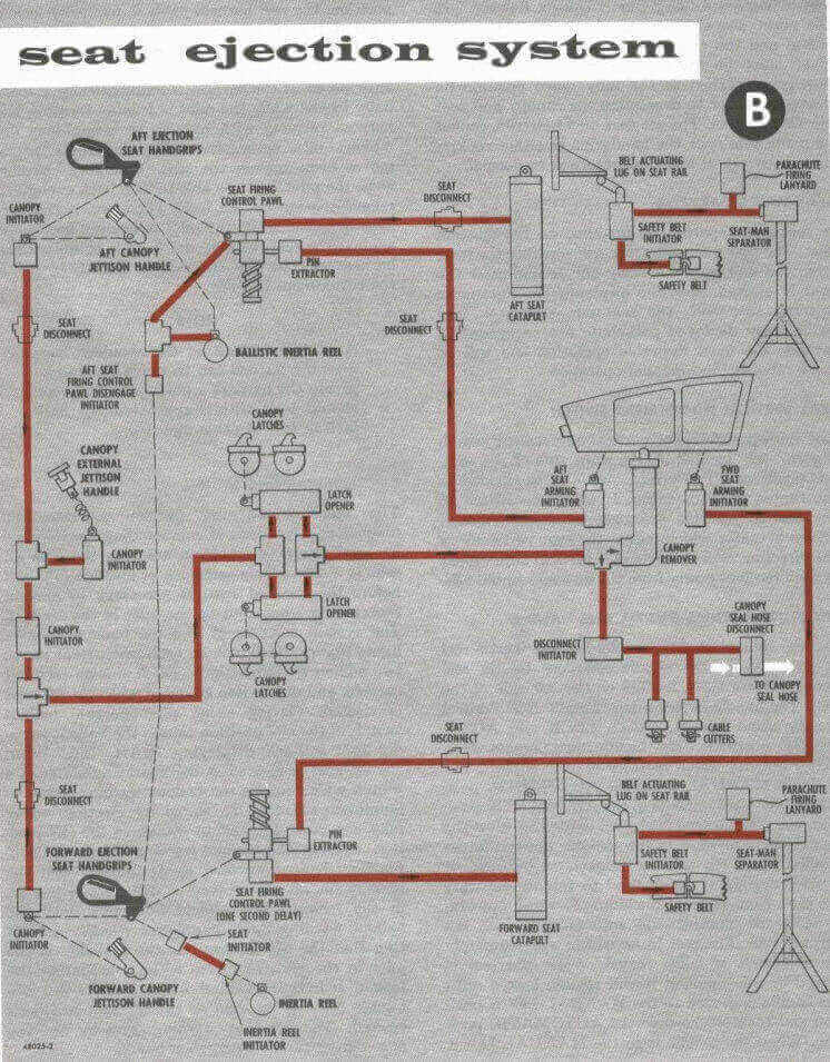
Ejection sequence
Squeezing the ejection hand grips on the arm rest handles caused the following events to occur:
Before 1979, locking of the shoulder harness inertia reel; after 1979, triggering of a M3A2 initiator located under the seat pan to power a shoulder harness retraction actuator. This device was a ballistic powered inertial reel and known by its initials BPIR. This action was to position the pilot’s back firmly against the seat.
As with the interim seat, the following events would occur using the same hardware but with upgraded initiator units:
Rotation of the spring-loaded arm guards to a horizontal position (see photo of the arm guards/paddles, in the vertical, “down” position).
Release of the M3A1-catapult initiator safety lock. This initiator was located under the left armrest and would be fired after the events described next.
Firing of the canopy unlatch-M3A1 initiator and canopy jettison: Ejection handle pull would activate an on-seat M3A1 canopy unlatch initiator for release of the canopy. This initiator was located under the right armrest and its hot gas was channeled to the canopy jettison hardware located off-seat through a ballistic hose coming out of the top-right portion of the seat. Firing of the canopy unlatch initiator resulted in the jettisoning of the canopy by hardware located off-seat. Upon leaving the aircraft, the canopy would pull a lanyard to activate an off-seat M3A1 initiator which in turn triggered the catapult phase. (Note: The small handle underneath the left hand firing handle is designed to actuate the on-seat M3A1 canopy unlatch initiator without firing the catapult.)
Catapult phase: The gas from this off-seat M3A1 initiator went through a ballistic hose routed to the top left portion of the seat. The gas activated a M1A1 exactor located next to the catapult initiator. The exactor pulled a safety pin from a seat-anchored spring, enabling the latter to pull the trigger rod of the M3A1 catapult initiator. The gas from the latter was then sent to the bottom of the ROCAT tube, through the lower hose on the left side of the seat, thus initiating the catapult phase. (Note that the safety pin refered to here is used to prevent catapult the M3A1 from being fired by the canopy jettison mechanism in case of the canopy being jettisoned manually.)
Seat travel up the rails and seat-man separation: As the seat traveled upwards, a seat-mounted lever was forced to rotate and fire a M-32 one-second-delay initiator. The lever and M-32 initiator were mounted under the seat pan (right-most initiator).
The novel features of the seat would then be activated:
After this one second delay, gas was released by the M-32 initiator into ballistic hoses connected to the lap belt, SMS strap rotator actuator, and parachute actuator. The gas caused the lap belt buckle to open, releasing both lap belt and shoulder harness end loops, thus releasing the pilot from all seat constraints. The gas also powered the SMS rotator to tension up the strap and cause separation of the pilot from the seat. The strap was initially routed behind the pilot and under his seat kit, and was attached to the front of the seat pan. Reeling-in the strap into the rotator actuator caused the strap to force the pilot out of the seat. Finally, the gas also activated the parachute actuator and the parachute deployment sequence as further described below.
Just before the seat cleared the rails, the rocket motor of the ROCAT system would fire and initiate the rocket phase of the ejection.
Two seconds after parachute actuator triggering and seat-man separation, the chute was forcibly deployed out of the back pack by the firing of a slug attached to the extraction chute (also called “drogue” chute or “pilot” chute). Upon deployment and inflation, the chute would extract the main parachute, a standard USAF C-9 hemispherical canopy of 28 ft diameter.
Project 90, A study in 0-0 Ejection
Zero-Zero - just about the lowest point in the Ejection Envelope. Sitting on the ground, with the aircraft immobile.An emergency arises and you don't have time to hop out of the cockpit and run. What can you do? How do you know the seat will work? Will it launch you high enough for the parachute to open? Will you be injured by the force of the launch?
These questions led to a unique test. In the mid-1960s a firm that had made its name providing ejection seats and egress technology to both the military and to NASA decided that instrumented dummies did not provide all the information needed. They felt that certain questions of human physiology needed to be answered by a test of a live human. Weber Aircraft's seats had saved over 500 lives by this time. They had been fitted to such varied craft as the F-106 and the Gemini Space capsule. The F-106 seat included the latest technologies available to allow for a clean ejection, including a gun deployed parachute, rocket motor, and self deploying survival equipment.
By Gordon Cress, Project Test Engineer: Project 90Zero-Zero - just about the lowest point in the Ejection Envelope. Sitting on the ground, with the aircraft immobile.An emergency arises and you don't have time to hop out of the cockpit and run. What can you do? How do you know the seat will work? Will it launch you high enough for the parachute to open? Will you be injured by the force of the launch?
These questions led to a unique test. In the mid-1960s a firm that had made its name providing ejection seats and egress technology to both the military and to NASA decided that instrumented dummies did not provide all the information needed. They felt that certain questions of human physiology needed to be answered by a test of a live human. Weber Aircraft's seats had saved over 500 lives by this time. They had been fitted to such varied craft as the F-106 and the Gemini Space capsule. The F-106 seat included the latest technologies available to allow for a clean ejection, including a gun deployed parachute, rocket motor, and self deploying survival equipment.
In late 1965, Jim Hall a professional parachute safety instructor and Major in the Air Force Reserve volunteered to act as the human guinea pig for the 0-0 seat package. He was instructed in all facets of the seat operation. He viewed films of the 43 sequential successful tests of the F-106 0-0 system. He also was measured for center of gravity in order to align the rocket exhaust with the center of mass of the man-seat package. In the tradition of the day, he visited the assembly line and selected the particular seat he would later ride.
The engineers checked and verified all functions of the particular seat. They selected a lake not far from the factory for the test. A set of seat rails were attached to a test stand. The date and time were selected. And then it was time.
Jim Hall, accompanied by a platoon of engineers, arrived at the site and was shown the seat. Now it was mounted on the rails, wired and ready to fire. Every mechanical function had been checked and double checked. Major Hall was attired in an orange flight suit. Its arms were cut away at the shoulder to reveal a small area of skin that had been marked by pigment. He was strapped into his chute and assisted into the seat. All the straps were connected and tightened. The engineering cameras were armed to record every aspect of the test, even the slump of Jim's shoulder markings under launch acceleration. Then the engineers withdrew to a safe distance. The rescue launches on the lake were signaled, and the countdown began...
Major Hall gripped the handles built into the sides of the seat bucket and pulled them up to the firing position... and nothing happened... for one long second. The delay cartridge allowed the high speed cameras to get to speed and then the hot gas was unleashed into the catapult initiator. The Major rose up the rails with anonset rate of 150 g's/second with a maximum of about 14g's. The rocket ignited as the seat cleared the rail providing the huge jet of flame in the above picture. One second and almost 400 feet later, seat separation occurred. The parachute gun fired, and two seconds later the parachute was fully inflated. The survival kit automatically released and dropped to the end of its lanyard. The rubber raft, suspended from the same lanyard,immediately inflated.
Approximately 26 seconds after Major Hall pulled the handles he landed in the lake.A journey of only a few dozen yards had taken him to an altitude of about 400 feet andinto the history books (albeit only a few obscure ones...). To this day, thirty-three years later, Jim Hall's zero-zero ejection test remains the only 0-0 test that was executedwith a human subject in the United States by an American Company. (The first known live 0-0 test was executed in 1961 by Martin-Baker Aircraft Co. Inc.. Doddy Hay, a M-B employee, was the 'Man in the Hot Seat' for that first test. There have been several other live tests, most of which have been at altitude, or with some airspeed.)
Approximately 26 seconds after Major Hall pulled the handles he landed in the lake.A journey of only a few dozen yards had taken him to an altitude of about 400 feet andinto the history books (albeit only a few obscure ones...). To this day, thirty-three years later, Jim Hall's zero-zero ejection test remains the only 0-0 test that was executedwith a human subject in the United States by an American Company. (The first known live 0-0 test was executed in 1961 by Martin-Baker Aircraft Co. Inc.. Doddy Hay, a M-B employee, was the 'Man in the Hot Seat' for that first test. There have been several other live tests, most of which have been at altitude, or with some airspeed.)
Info provided by Gordon Cress, Project 90 Test Engineer via The Ejection Seat Website by Kevin Coyne
Parachute system
The parachute system involved the pilot wearing a modified BA-18 automatic-type parachute back pack containing the C-9 parachute and a MA-1 type extraction chute. The modifications to this parachute pack included:
The removal of the so-called “quarter bag”, which kept the mouth of the C-9 parachute closed until complete deployment of the suspension lines. The quarter bag was used to delay parachute opening and thus prevent high opening shocks during high speed bailouts. Quarter bag removal insured swift parachute opening at the low speeds characteristic of 0-0 ejections, which by 1965 had become the highest priority in seat design.
A gun barrel assembly for the firing of a 13oz. slug tied to the parachute extraction chute. Gun firing occurred only under 15,000’ and only after a 2-second delay following seat-man separation. The gun was controlled by an aneroid altimeter unit and was bolted inside the parachute pack.
A spring-loaded extraction chute tied to the gun slug via tubular lanyard, of a type different from the standard MA-1 extraction chute.
The standard extraction chute kicker plate was also modified with the addition of two grommeted tabs through which the top two pack closing loop were routed. This arrangement prevented the motions of the extraction chute inside the pack when the pilot moved against the seat.
The gun barrel and slug were located on the upper right corner of the parachute pack. The parachute included hardware that allowed parachute deployment to be activated manually, or by the firing of the drogue gun. The manual mode would be initiated by the pilot pulling the T-shaped “anti-blast” handle and ripcord cable. In the manual mode, the drogue chute would spring out on its own, being disconnected from the gun slug. Note that the gun slug would still be fired by the aneroid unit below 15,000 ft in the manual mode, this time without being connected to the extraction chute.
The gun-aneroid assembly was connected to a cable, which came out of the left side of the parachute pack. The other end of the cable was directly connected to left side of the seat to a hardware unit called the parachute actuator. The latter effected the actuation of the drogue-gun altimeter unit using gas from the M32 initiator unit located under the seat. The parachute actuator actually performed two functions, namely that of grabbing and pulling the cable for altimeter activation, and then releasing the cable during seat-man separation.
Seat modifications over the years
To improve seat performance and reliability, as well as to adapt the escape system to evolving USAF requirements, a series of modifications were carried out on all Century jet seats over the years. In the case of the F-106 zero-zero seat, these included the following:
During the late 1960’s or early 1970’s:
The replacement of the MA-6 lap belt by the HBU-4A belt. The seat shown here still features the MA-6 lap belt and its ballistic hose connecting to the M32 initiator under the seat pan.
From 1975 through 1988:
In 1978, installation of a smaller and simpler “elbow”-shaped seat-mounted parachute actuator. The seat shown here features this more recent elbow parachute actuator. Note that the MA-6 lap belt also shown in the photograph with the elbow actuator is actually an historical mismatch; an HBU-4A belt would have been more appropriate.
In 1979, the shoulder harness inertia reel system was replaced by a gas-powered (or “ballistic”) shoulder harness retraction reel, which caused automatic and proper positioning of the pilot against the seat. The gas generator and reel motor were installed behind the seat headrest. This modification also required the installation of a M3A2 initiator under the seat pan (photo, leftmost initiator). Triggered by the rotation of a torque tube upon ejection handle pull, the M3A2 sent gas to activate the shoulder harness retractor initiator.
The removal of the chaff dispenser from the upper right side of the seat.
Installation of a metal strap ROCAT protector.
Removal of the ditching lever. This lever allowed the pilot to manually disconnect the parachute deployment cable from the seat-mounted parachute actuator. Its removal followed the conversion to the elbow-type parachute actuator.
In 1983, replacement of the HBU-4A lap belt by the HBU-12A lap belt (not shown on the photos).
The Ejection Seat Website by Kevin Coyne